Creating a venue with custom indoor routing
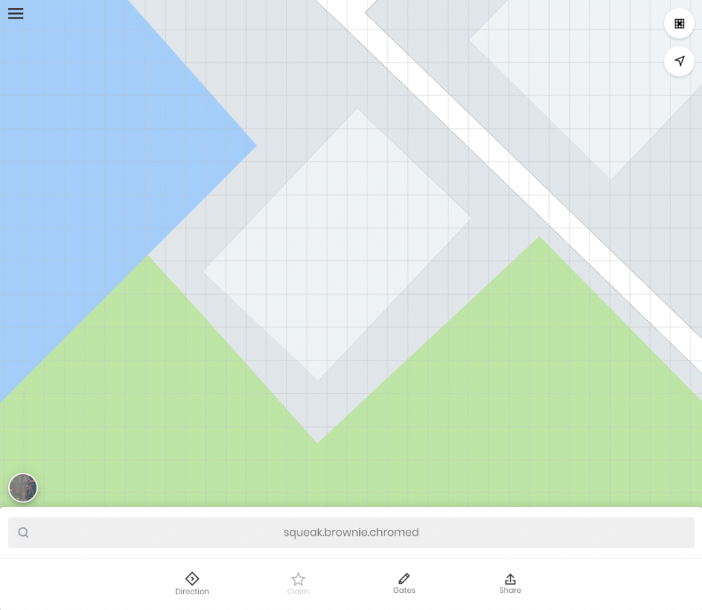
Using the UNL api it is simple to to add a custom venue with indoor routing. In this tutorial we will add our own simple venue and configure indoor routing. The building below is not listed in the UNL venue database, so lets create a definition for it.
Venue#
The Venue model has the following structure, at the top level we include basic metadata about the venue. Names and addresses are localised, which the language being identified by its 3 character ISO 693-2/B code. At a minimum a venue consists of this basic metadata and at least one level.
Levels#
The levels array defines each level (or floor) in the venue. A level consists on one or more outer areas, for our current example we will work with a single outer area to keep things simple.
Each outer area has the following 3 components:
- A polygon defining the shape of the area, this polygon is specified as a list of UNL cell id's.
- An array of spaces: used to identify particular rooms, or areas within the venue.
- A routing graph, used to define the points of access and indoor routing for the outer area.
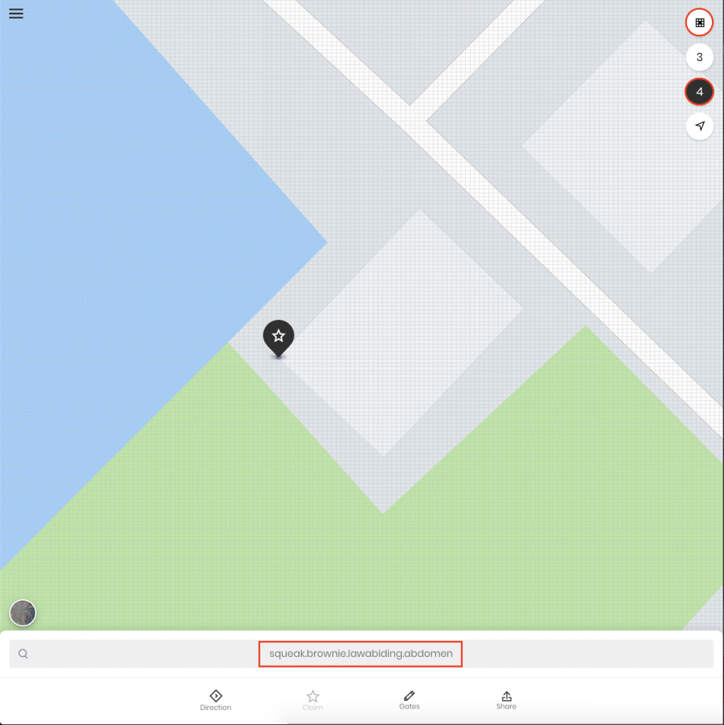
To define the polygon for your outer area, open the UNL map and change the precision to 4 words by using the precision button at the top right of the UI and selecting 4. Then click on the cell where you want to start your polygon, the cell id will display in the search box, copy this cell id into your polygon array. (Note, the first and last item in the polygon should match).
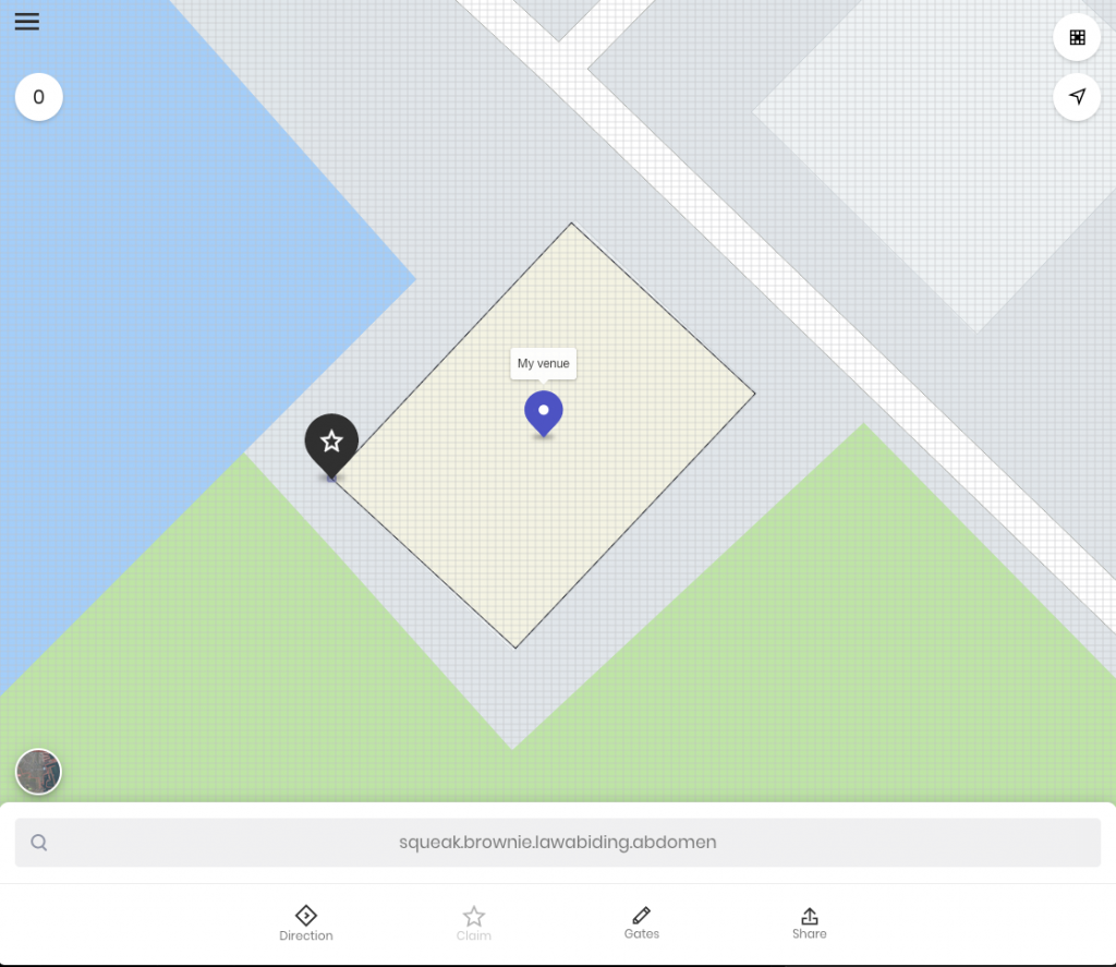
At this point it is possible to POST the venue model to UNL and see it displayed on the map.
Next we will add a space to our mode; let's assume there is a cafe on the ground floor of this building. We may add the cafe space to our outer area with this simple model. Note, identifier must be unique within the venue, you may wish to use a uuid here if you are adding many spaces.
Next we can configure our routing graph. The routing graph consists of 2 arrays, vertices, and edges.
Vertices defines a list of nodes in the graph. If the vertex has property direction it is treated as an accessor, the possible values for direction are ENTER-EXIT, EXIT-ONLY, ENTER-ONLY, or NO-ENTRY. If the vertex also has the property spaces it is an accessor to that space. This is an array as you may have a door between 2 adjacent spaces. As with spaces, the identifiers must be unique in the venue.
Edges defines the connections between nodes. In this simple routing graph we can navigate from the venue entrance through the hallway and onto the cafe on the ground floor.
After posting the complete level with spaces and routing graph it is possible to navigate to the cafe with indoor navigation.
Connectors#
Connectors allow us to add connections between levels in the venue. The supported connector classes are SKYWALK, ELEVATOR, ESCALATOR, RAMP, STAIRS, SHUTTLE, MOVINGSIDEWALK, and OTHER. Following a similar structure to the routing graph vertices we can define a chain of accessors for each level.
Navigate#
After posting our completed sample venue we can make use of indoor navigation by placing the cell selector in the desired space, and clicking directions.